SE Data Plane Architecture and Packet Flow
Overview
This user guide explains the details of Service Engine data plane architecture and packet flow.
The Data Plane Development Kit (DPDK) comprises a set of libraries that boosts packet processing in data plane applications.
The following are the packet processing for SE data path:
-
Server health monitor
-
TCP/IP Stack - TCP for all flows
-
Terminate SSL
-
Parse protocol header
-
Server load balancing for SIP/L4/L7 App profiles
-
Sending and receiving packets
SE System Logical Architecture
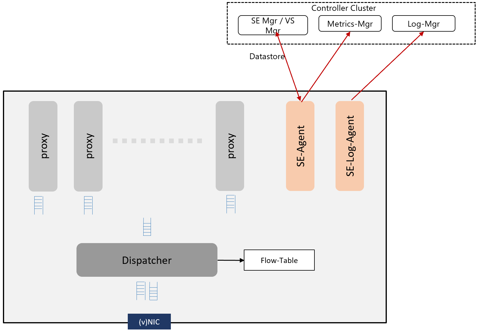
The following are the features of each components in SE system logical architecture:
- Process — The following are the 3 processes in Service Engine:
- SE-DP
- SE-Agent
- SE-Log-Agent
- Work Process
-
SE-DP — The role of the process can be proxy-alone, dispatcher-alone, proxy-dispatcher combination.
-
Proxy-alone — Full TCP/IP, L4/L7 processing and policies defined for each app/virtual service.
-
Dispatcher-alone —
-
Processes Rx of (v)NIC and distributes flows across the proxy services via per proxy lock-less RxQ based on current load of each proxy service.
-
Dispatcher manages the reception and transmission of packets through the NIC.
-
Polls the proxy TxQ and transacts to the NIC.
-
-
Proxy-dispatcher — This acts as a proxy and dispatcher depending on the configuration and resources available.
-
-
SE–Agent — This acts as a configuration and metrics agent for Controller. This can run on any available core.
-
SE-Log-Agent — This maintains a queue for logs. This performs the following actions:
- Batches the logs from all SE processes and sends them to the log manager in Controller.
- SE-Log-Agent can run on any available core.
-
-
Flow-Table — This is a table that stores relevant information about flows.
- Maintains flow to proxy service mapping.
Based on the resources available, the service engine configures optimum number of dispatchers. You can override this by using Service Engine group properties. There are multiple dispatching schemes supported based on the ownership and usage of NICs.
-
A single dispatcher process owning and accessing all the NICs.
-
Ownership of NICS distributed among a configured number of dispatchers.
-
Multi-queue configuration where all dispatcher cores poll one or more NIC queue pairs, but with mutually exclusive se_dp to queue pair mapping.
The remaining instances are considered as proxy. The combination of NICs and dispatchers determine the PPS that a SE can handle. The CPU speed determines the maximum data plane performance (CPS/RPS/TPS/Tput) of a single core, and linearly scales with the number of cores for a SE.
You can dynamically increase the SE’s proxy power without the need to reboot. A subset of the se_dp processes are active in handling the traffic flows. The remaining se_dp processes will not be selected to handle new flows. All the dispatcher cores are also selected from this subset of processes.
The number of active number of se_dp processes can be specified using SE group property max_num_se_dps. As a run-time property, it can be increased without reboot. However, if the number is decreased, it will not take effect until after the SE is rebooted.
The following is the configuration example:
[admin:ctr2]: serviceenginegroup> max_num_se_dps

INTEGER 1-128 Configures the maximum number of se_dp processes that handles traffic. If not configured, defaults to the number of CPUs on the SE.
[admin:aziz-tb1-ctr2]: serviceenginegroup> max_num_se_dps

INTEGER 1-128 Configures the maximum number of se_dp processes that handles traffic. If not configured, defaults to the number of CPUs on the SE.
[admin:ctr2]: serviceenginegroup> max_num_se_dps 2
[admin:ctr2]: serviceenginegroup> where | grep max_num
| max_num_se_dps                        | 2                     |
[admin:ctr2]: serviceenginegroup>
Tracking CPU Usage
CPU is intensive in the following cases:
- Proxy
- SSL Termination
- HTTP Policies
- Network Security Policies
- WAF
- Dispatcher
- High PPS
- High Throughput
- Small Packets (for instance, DNS)
Packet Flow from Hypervisor to Guest VM
SR-IOV
Single Root I/O Virtualization (SR-IOV) assigns a part of the physical port (PF - Platform Function) resources to the guest operating system. A VF (VF - Virtual Function) is directly mapped as the vNIC of the guest VM and the guest VM needs to implement the specific VF’s driver.
SR-IOV is supported on CSP and OpenStack no-access deployments.
For more details on SR-IOV, refer to SR-IOV with VLAN and Avi Vantage (OpenStack No-Access) Integration in DPDK.
Virtual Switch
Virtual switch within hypervisor implements L2 switch functionality and forwards traffic to each guest VM’s vNIC. Virtual switch maps a vLAN to a vNIC or terminates overlay networks and maps overlay segment-ID to vNIC.
Note: AWS/Azure clouds have implemented the full virtual switch and overlay termination within the physical NIC and network packets bypass the hypersivor.
In these cases, as VF is directly mapped to the vNIC of the guest VM, guest VM needs to implement specific VF’s driver.
VLAN Interfaces and VRFs
VLAN
VLAN are logical physical interfaces that can be configured with an IP address. This acts as child interfaces of the parent vNIC interface. VLAN interfaces can be created on port channels/bonds.
VRF Context
A VRF identifies a virtual routing and forwarding domain. Every VRF has its own routing table within the SE. Similar to a physical interface, a VLAN interface can be moved into a VRF. The IP subnet of VLAN interface is part of the VRF and its routing table. The packet with a VLAN tag is processed within the VRF context. Interfaces in two different VRF contexts can have overlapping IP addresses.
Health Monitor
Health monitors run in data paths within proxy as synchronous operations along with packet processing. Health monitors are shared across all the proxy cores, hence linearly scales with the number of cores in SE.
For instance, 10 virtual services with 5 servers in a pool per virtual service and one HM per server is 50 health monitors across all the virtual services. 6 core SE with dedicated dispatchers will have 5 proxies. Each proxy will run 10 HMs and all the HM status is maintained within shared memory across all the proxies.
Custom external health monitor runs as a separate process within SE and script provides HM status to the proxy.
DHCP on Datapath Interfaces
The DHCP mode is supported on datapath interfaces (regular interfaces/bond) in baremetal/LSC Cloud. Starting with Avi Vantage version 20.1.3, it can also be enabled from Controller GUI.
You can enable DHCP from the Controller using the following command:
configure serviceengine <serviceengine-name>
You can check the desired data_vnics index ( i ) using the following command:
data_vnics index <i>
dhcp_enabled
save
save
This should enable DHCP on the desired interface.
To disable DHCP on a particular data_vnic, you can replace dhcp_enabled by no dhcp_enabled in the above command sequence.
Note: If DHCP is turned-ON on unmanaged/ unconnected interfaces, it could slow down the SE stop sequence and SE could get restarted by the Controller.